Formula SAE Cooling Systems
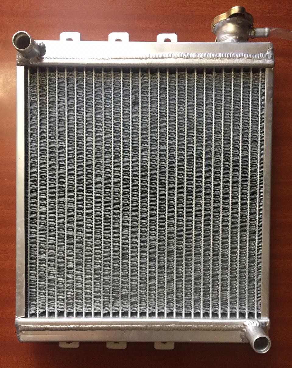
Previous season, we used a KTM 390 stock radiator and radiator fan. The problem faced last year was insufficient cooling, which caused overheating of the engine, which affected the performance of the car. Moreover, the stock Cooling system was designed for bikes and was not capable of cooling the engine in a Formula Car, which has to perform with a large load, and thus the heat ejected was more for efficient performance. Hence, our team felt the need to change the cooling system for better cooling of the engine. The goal for this year’s vehicle is to have a simple, reliable, and well-built vehicle that can respectably compete at the Formula SAE competition in Coimbatore, India.
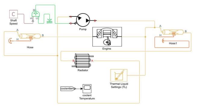
This model uses an engine cooling system using thermal liquid blocks. Heat from the engine is absorbed by the water coolant and dissipated through the radiator. The thermal liquid blocks include the Fluid Jacket, pump, and radiator. The model is developed in MATLAB Simulink.
The fluid jacket and the Radiator are modifications of the Pipe (TL) block. These components represent an internal volume of liquid to model the effects of dynamic compressibility and thermal capacity using the mass and energy conservation equations. Default priorities for the pressure and temperature are set to high to provide initial conditions for the liquid state.
All four components inherit from foundation.thermal_liquid.two_port_dynamic or foundation.thermal_liquid.two_port_steady base classes, which implement common equations to calculate the energy flow rate based on a smoothed upwind method. This method allows energy to be convected downstream, enabling the proper propagation of information throughout the thermal liquid network.
This block models a fluid jacket in a thermal liquid network that absorbs heat from its surroundings. It assumes that there is a non-negligible volume of liquid inside the jacket to model the effects of dynamic compressibility and thermal capacity. The heat exchange is calculated based on a Nusselt number correlation. Port H, the thermal conserving port, represents the surface through which heat transfer occurs.
Simulation and actucal coolant temperature were evaluated by assembling thermocouples in the bottom coolant tank of the heat exchanger; both data were compared and didn't show any considerable difference.
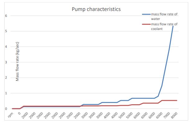
This graph was obtained by using a mass flow sensor. A sensor was attached to the cooling system between the hoses to differentiate the mass flow rate between coolant and distilled water. Due to the change in viscosity of both fluids, as coolant becomes more viscous, pumps require a bit more power to circulate coolant in the system. This results in a decrease in mass flow rate, which eventually alters the heat transfer capacity of the cooling system.